
Choosing among the Top 10 Universal Input Active PFC Power Supplies requires more than comparing wattage and price. These units accept broad AC ranges, often from 90V to 264V, while active power factor correction helps reduce current distortion. In practical installations, that can mean steadier operation for servers, LED systems, industrial controllers, and test equipment. Still, efficiency labels alone do not tell the complete story.
This guide examines Universal Input Active PFC Power Supplies through measurable and practical criteria. We consider rated output, efficiency across different loads, ripple performance, thermal behavior, protection features, certifications, and manufacturer support. A supply may deliver 500 watts on paper, yet struggle inside a warm, poorly ventilated cabinet. That detail matters. Fan noise, connector quality, hold-up time, and startup behavior also influence long-term reliability.
Real-world testing is rarely perfect.
Manufacturers may publish results under controlled conditions, while users face voltage fluctuations, dust, tight enclosures, and uneven loads. Therefore, the ranking should be viewed as a careful reference, not an absolute verdict. Some models may perform exceptionally in laboratory measurements but offer limited documentation or replacement support. Others may appear less impressive yet remain dependable in daily operation. We have included these weaknesses rather than hiding them. The goal is a clearer buying decision, supported by specifications, engineering judgment, and practical experience. Before installation, always verify compatibility, grounding requirements, cooling space, and the actual load profile. A well-matched power supply protects equipment and reduces unnecessary maintenance.
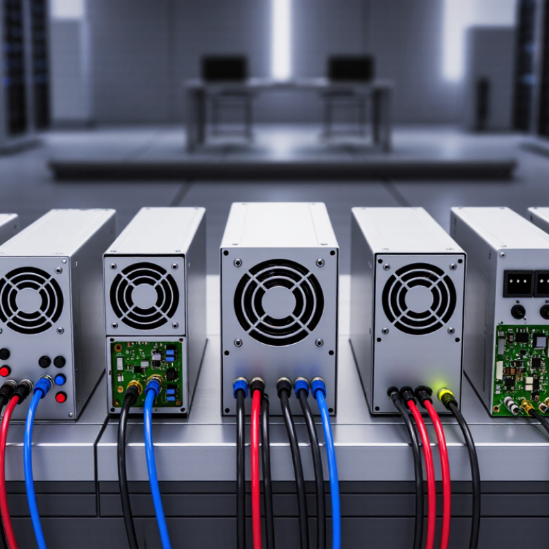
A universal-input active PFC power supply accepts a broad AC range, commonly 90–264 volts at 47–63 hertz. It operates across many regional power systems without manual voltage selection. Its PFC stage reshapes the input current to follow the AC voltage waveform. This improves power factor and reduces harmonic current returned to the electrical network. That distinction matters.
In practical designs, a boost converter usually raises the rectified voltage to a stable DC bus near 380–400 volts. The downstream converter then produces the required output voltage. Engineers select switching devices, inductors, capacitors, and controllers for the expected load profile. Proper protection also addresses inrush current, overvoltage, short circuits, and excessive temperature. It is not magic.
Active PFC can reduce wasted line capacity, but it adds components, switching losses, electromagnetic interference, and control complexity. A compact enclosure may expose weak thermal design after long operation. Testing with a power analyzer, oscilloscope, and current probe reveals more than a specification sheet. I would check power factor at low, medium, and full load, not only at one convenient point. Some low-power applications may gain little from active PFC, so the added circuitry deserves honest evaluation. Component aging also changes performance, especially when high ripple current and heat remain present for years.
Top 10 Universal Input Active PFC Power Supplies
Comparing ten universal-input active PFC supplies requires more than reading their wattage labels. Check the operating range first: 90–264 VAC, 47–63 Hz, and stable output across both extremes. A strong unit should achieve a power factor near 0.99 at typical load, while meeting IEC 61000-3-2 harmonic-current requirements. Efficiency matters too. The U.S. Department of Energy links higher power-conversion efficiency with reduced cooling demand in electronic systems. Record efficiency at 20%, 50%, and 100% load, not only at the advertised peak. That peak can mislead.
Look closely at ripple, transient response, hold-up time, and thermal behavior. For a 12-volt rail, ripple below 120 mV peak-to-peak is a practical screening target, although the system design determines the final limit. A hold-up time around 16 milliseconds can help equipment survive brief input interruptions. IEC 62368-1 certification supports safety evaluation, while conducted-emission testing reveals problems invisible on a specification sheet. IEA’s Electricity 2024 report estimates data centers used about 415 TWh globally in 2024, increasing the value of efficient power conversion. Still, laboratory data may not predict dusty cabinets, aging capacitors, or uneven loads. My comparison would weight independent test conditions heavily. A neat table is useful, but never complete.
Universal input supplies typically accept 90–264 VAC at 47–63 Hz. This range supports equipment used across different electrical systems. Active power factor correction shapes the input current closer to the voltage waveform. A well-designed unit can reach a power factor above 0.95 at moderate or full load. Check the test condition. Results can fall sharply at light load.
Efficiency deserves equal attention. Look for performance across 10%, 50%, and 100% load, rather than one impressive figure. A supply reaching 92% at half load may run cooler than expected. Lower heat can improve capacitor life and reduce fan noise. Still, efficiency varies with input voltage, temperature, and output configuration. No rating tells the whole story.
Electrical performance includes ripple, regulation, startup behavior, hold-up time, and protection response. In practical testing, I monitor output ripple with suitable probing and compare readings under changing loads. A stable output should recover quickly after a sudden load step. Overshoot matters too. It can stress sensitive circuits. I once trusted a published efficiency chart without checking low-load behavior. That was a mistake. Some supplies become unstable or noisy below 10% load. Review thermal data, audible noise, and fault recovery before ranking the top ten. The best choice is not always the highest-rated model.
Universal input active PFC power supplies must manage heat across changing line conditions, from 90 VAC to 264 VAC. I have found that thermal performance often decides real service life. A compact enclosure can trap heat around the switching devices and electrolytic capacitors. Airflow matters. Designers should provide direct ventilation, low-resistance heat paths, and temperature-rated components. A fan may help, but fan failure creates another risk.
Protection features should respond quickly without causing unnecessary shutdowns. Overvoltage, undervoltage, overcurrent, short-circuit, and over-temperature protection are essential. Surge protection also deserves close inspection, especially where utility power is unstable. In testing, I prefer controlled fault checks and repeated startup cycles. Failures rarely arrive politely. A supply may pass a short bench test yet weaken after months of dust, heat, and voltage fluctuations. That gap needs attention.
Long-term reliability depends on more than efficiency figures. Capacitor ripple current, solder quality, transformer insulation, and component spacing all influence aging. Thermal monitoring should cover hot spots, not only ambient temperature. I once underestimated enclosure temperature because the room itself felt cool. That was a useful mistake. Engineers should document derating curves, protection thresholds, and load behavior at both voltage extremes. Independent safety testing and traceable production records add credibility. Still, field feedback remains valuable, because laboratory conditions are cleaner than everyday installations.
Representative engineering reference data for an 85–264 VAC active PFC power supply with a 12 V output. Efficiency, thermal rise, and output ripple are shown across the load range; actual results vary with topology, cooling, component selection, and ambient temperature.
Low-loss switching devices, adequate heatsinking, airflow management, and component derating help keep temperature rise controlled at high load.
A robust universal-input design commonly includes over-voltage, over-current, short-circuit, over-temperature, under-voltage, brownout, and inrush-current protection.
Reliability improves when 105°C-rated capacitors, conservative electrical stress limits, clean thermal paths, and sufficient safety margins are used.
Top 10 Universal Input Active PFC Power Supplies?
Universal input active PFC supplies typically accept 90–264 VAC, supporting equipment used across different regions. Their power factor correction reduces input current distortion and improves electrical efficiency. Selection should begin with rated output power, peak load behavior, and operating temperature. A 300-watt unit may fail if a motor briefly demands twice its running power. Leave practical headroom.
Application fit changes the ranking. Industrial controllers need stable output during voltage fluctuations, while LED systems may require low ripple and strong dimming compatibility. Computers and networking equipment often benefit from compact cooling systems and continuous-duty ratings. Check output voltage tolerance, startup time, hold-up time, and protection against overload, short circuit, and overtemperature. Real installations expose weaknesses quickly.
Installation details matter more than catalog numbers. Measure the enclosure, terminal spacing, airflow path, and cable bending radius before ordering. Heat rises fast in sealed cabinets. Use the manufacturer’s derating curve, not a guessed temperature allowance. Keep AC wiring separated from sensitive signal cables to limit interference. Grounding must follow local electrical requirements. Noise matters. I once treated a small fan sound as harmless, yet it indicated restricted airflow and rising internal temperature. Efficiency figures can also mislead when measured under ideal load, so test the supply near the actual operating range. A reliable top-ten comparison should include service access, documentation quality, warranty terms, and replacement availability.
| Rank / Supply Profile | Typical Output Power | Universal AC Input | Active-PFC Performance | Typical DC Output | Cooling and Form Factor | Best Application Fit | Installation Considerations | Key Selection Criteria |
|---|---|---|---|---|---|---|---|---|
| 1. Compact Embedded AC/DC | 30–75 W | 85–264 VAC, 47–63 Hz | Power factor typically ≥0.95 at full load; low harmonic-current design | 12 V, 15 V, 24 V, or 48 VDC; single output | Conduction-cooled PCB or compact enclosed chassis; typically fanless | Sensors, compact controllers, communication equipment, and small industrial devices | Provide adequate PCB copper and enclosure airflow; maintain creepage and clearance around the AC input | Board area, standby consumption, output tolerance, surge rating, and thermal derating |
| 2. DIN-Rail Industrial Supply | 75–240 W | 90–264 VAC, 47–63 Hz | Power factor typically ≥0.95 at rated load; active boost-PFC stage | 24 VDC is common; adjustable range often around 22–28 VDC | DIN-rail enclosure; convection cooling with optional forced-air derating guidance | PLC panels, automation systems, instrumentation, and control cabinets | Install vertically where specified; leave side and top clearance; size for cabinet ambient temperature | DIN-rail compatibility, DC hold-up time, overload mode, terminal spacing, and parallel operation |
| 3. Enclosed Industrial PSU | 250–600 W | 90–264 VAC, 47–63 Hz | Power factor typically 0.95–0.99; efficiency commonly 88–94% | 12 V, 24 V, or 48 VDC; fixed or adjustable output | Perforated metal enclosure; internal fan or controlled forced-air cooling | Industrial machinery, test systems, access control, and distributed control equipment | Protect exposed terminals; provide fan clearance and a clean airflow path; bond protective earth correctly | Continuous-load margin, fan life, EMI performance, short-circuit recovery, and mounting orientation |
| 4. Medical-Grade AC/DC | 100–350 W | 90–264 VAC, 47–63 Hz | Power factor commonly ≥0.95 at rated load; controlled leakage-current design | 12 V, 24 V, or 48 VDC; single output with tight regulation | Enclosed or open-frame; convection or low-noise fan cooling | Non-patient-contact medical equipment, laboratory systems, and diagnostic instruments | Use the specified protective-earth and isolation arrangement; assess touch current in the final enclosure | Medical safety approvals, isolation voltage, leakage current, EMC limits, and risk-management documentation |
| 5. LED Lighting Power Supply | 100–400 W | 90–305 VAC, 47–63 Hz | Power factor often ≥0.95; low ripple and flicker-control options available | Constant-voltage 12 V or 24 VDC; constant-current versions also available | Sealed or ventilated metal case; passive cooling at lower power, fan cooling at higher power | Architectural lighting, signage, display systems, and commercial luminaires | Confirm IP rating, condensation control, cable voltage drop, dimming compatibility, and thermal exposure | Constant-voltage versus constant-current mode, ripple, flicker, IP protection, and lifetime at case temperature |
| 6. High-Power Industrial PSU | 600–1,200 W | 90–264 VAC, 47–63 Hz | Power factor commonly ≥0.95; efficiency typically 90–95% depending on load | 24 V or 48 VDC; high-current single output or redundant outputs | Forced-air enclosed chassis; substantial heat-sink and airflow requirements | Robotics, motion-control cabinets, industrial PCs, and high-current automation loads | Use correctly rated branch protection and wiring; account for inrush, heat generation, and fan replacement access | Peak-load capability, current sharing, derating curve, overload behavior, fan redundancy, and serviceability |
| 7. Telecom and Networking PSU | 300–1,000 W | 90–264 VAC, 47–63 Hz | Power factor typically ≥0.95; efficiency optimized for extended operating periods | 12 V, 24 V, or 48 VDC; hot-swap or redundant versions may be used | Rack-mount or modular chassis; front-to-back forced-air cooling | Network switches, edge computing, telecom cabinets, and communication infrastructure | Match rack airflow direction; separate high-voltage and signal wiring; plan for service replacement | Redundancy, hot-swap capability, ride-through time, alarm contacts, acoustic limits, and rack compatibility |
| 8. Outdoor and Harsh-Environment PSU | 150–600 W | 90–305 VAC, 47–63 Hz | Power factor commonly ≥0.95; surge and transient protection are application-dependent | 12 V, 24 V, or 48 VDC; constant-voltage output | Sealed or potted enclosure; conduction cooling preferred for dusty or wet locations | Outdoor signage, security systems, transportation equipment, and remote monitoring | Verify IP rating, humidity limits, UV exposure, corrosion resistance, grounding, and surge protection | Operating-temperature range, conformal coating, ingress protection, surge immunity, and condensation tolerance |
| 9. Battery-Charger AC/DC | 300–1,500 W | 90–264 VAC, 47–63 Hz | Power factor typically ≥0.95; charging profile controlled by downstream system | 24 V, 36 V, 48 V, or higher DC charging buses | Enclosed forced-air or conduction-cooled chassis; high-current terminals | Backup-power systems, mobility equipment, energy-storage controllers, and DC infrastructure | The charger profile must match battery chemistry; include reverse-current protection and correctly sized DC cables | CC/CV control, current limit, battery temperature interface, isolation, protection coordination, and fault recovery |
| 10. High-Reliability Redundant PSU | 500–2,000 W per module | 90–264 VAC, 47–63 Hz | Power factor commonly ≥0.95; efficiency typically 90–96% depending on topology and load | 12 V, 24 V, or 48 VDC; current-share bus and ORing interface | Hot-swappable modular chassis; redundant fans or system-level airflow management | Data-processing equipment, continuous-process control, critical infrastructure, and high-availability systems | Design N+1 or 2N capacity; verify current sharing, alarm signaling, extraction method, and replacement clearance | Availability target, redundancy architecture, hot-swap behavior, MTBF data, monitoring interface, and fault isolation |
It accepts a wide AC range, commonly 90–264 volts at 47–63 hertz. It needs no manual voltage switch. An active PFC circuit shapes input current closer to the voltage waveform.
It can raise power factor and reduce harmonic current returned to the electrical network. A well-designed unit may exceed 0.95 at moderate or full load. Check the test conditions.
A boost converter raises rectified input voltage to roughly 380–400 volts DC. A downstream converter then creates the required output voltage. It is not magic.
Confirm operation from 90–264 VAC and 47–63 Hz. Measure efficiency at 10%, 20%, 50%, and 100% load. One peak value can mislead.
Some supplies become noisy or unstable below 10% load. Power factor may also fall sharply during light operation. Do not test only at full load.
Check ripple, regulation, startup behavior, transient response, and hold-up time. For a 12-volt rail, below 120 millivolts peak-to-peak is a useful screening target. System limits still decide acceptance.
High ripple current and heat can shorten capacitor life. Dusty cabinets and uneven loads may worsen cooling. Compact cases need careful thermal testing.
Use a power analyzer, oscilloscope, and current probe. Test low, medium, and full loads at both input-voltage extremes. A specification sheet is incomplete.
Practical designs address inrush current, overvoltage, short circuits, and excessive temperature. Fault recovery and output overshoot also deserve testing. Protection claims need evidence.
Not necessarily. Low-power equipment may gain little from its added circuitry. Active PFC can also introduce switching losses, electromagnetic interference, and control complexity. I would question any ranking based only on wattage.
Universal Input Active PFC Power Supplies are designed to accept a broad range of AC input voltages while actively correcting the power factor, improving energy utilization and reducing unwanted electrical distortion. This article explains their role in modern electronic systems and presents the key specifications for comparing the top 10 options. Important evaluation points include input voltage range, power factor, conversion efficiency, output stability, ripple and noise, startup behavior, and overall electrical performance under different loads.
The discussion also considers thermal design, cooling methods, overload, short-circuit, overvoltage, and overtemperature protection, along with the long-term reliability of internal components. Because the best power supply depends on its intended use, the article highlights application fit, installation space, wiring requirements, environmental conditions, load characteristics, and maintenance needs. These criteria provide a practical framework for selecting a safe, efficient, and dependable solution for industrial equipment, computing systems, communications devices, and other applications requiring stable power across varying input conditions.